function
(Vout/Vin)
NON-ISOLATING DC-DC CONVERTERS

(0<D<1)

(0<D<1)

(0<D<1)
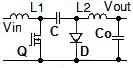
(0<D<1)

(0<D<1)
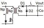
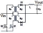
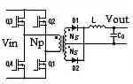
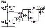
ISOLATING DC-DC CONVERTERS

(2Lp×F ×Iout)
(0<D<1)
flyback

(2Lp×F ×Iout)
(0<D<1)
(0<D<0.5)
forward

(0<D<0.5)
clamp
forward

(0<D<1)
bridge

(0<D<0.5)
pull
(D<0.5)
(0<D<0.5)
full bridge
(0<D<0.5)
half bridge
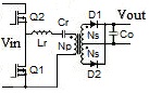
(at F=Fres)
1. All formulas are given for ideal circuits. Ripple currents, voltage spikes, power losses, voltage drops in MOSFETs and diodes are excluded.
2. Transfer function for phase shifted bridge uses effective ("overlapping") duty cycle.
3. For LLC converter the formulas are given for operation at resonance.
4. SUR is total switch utilization ratio defined as SUR=Pout/n×Vmax×Imax, where n- the number of power switches in the circuit, Vmax and Imax- their peak voltage and current.