CALCULATING SPACING BETWEEN PCB TRACES FOR VARIOUS VOLTAGE LEVELS
CIRCUIT BOARD LAYOUT GUIDELINES
Proper distances between PCB traces are critical to avoid flashover or tracking between electrical conductors. Unfortunately, there is no single solution to this issue. There is a variety of industry and safety standards that prescribe different spacing requirements depending on the voltage, application and other factors. Here I am providing some considerations and a simple WIDGET that will help you determine the proper spaces between PCB tracks.SAFETY REQUIREMENTS
When a product has to be recognized by a certain safety agency,
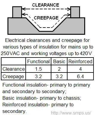
The required grade depends on the location of the circuit. The standard specifies functional, basic, supplementary, double and reinforced insulations. For example, when a breakdown can create a hazardous voltage on user accessible conductive parts (such as in case of insulation between mains circuits and low-voltage secondary circuits), a double or reinforced insulation is required. In this case, to separate such circuits on the PCB you need to double the respective distances shown in an appropriate table. The diagram below illustrates the clearance and creepage measurements. It lists as an example the requirements (in mm) for a typical application with AC mains 250Vrms, peak working voltages under 420V, and peak AC mains transients up to 2.5kV. Note that 1 mm ≈ 40 mils. If you don't have an access to the UL document, this creepage calculator will help you find the necessary distance. Of course, you should consult with UL 60950-1 or an applicable standard for final design decisions. Note that for the equipment manufactured in China and intended for use at altitudes above 2,000m (up to 5,000m), according to GB 4943.1-2011 the minimum distances has to be multiplied by 1.48.
OPERATIONAL REQUIREMENTS
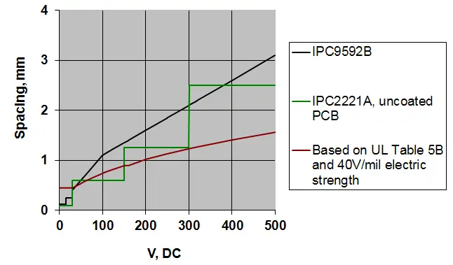
The distances provided by IEC and UL actually greatly exceed the spacing necessary for proper operation of the devices. This was done in order to provide increased protection against electric shock. For the circuits whose locations do not require electric shock protection, spacing between printed circuit tracks can be made smaller.
For the so called functional insulation, UL permits to use separation distances lesser than the specified in their charts. They just have to withstand the electric strength test (casually called Hipot) per Par.5.2.2 Table 5B.